Electrical machinery (commonly known as "motor") refers to an electromagnetic device that converts or transmits electrical energy according to the law of electromagnetic induction and is used to generate driving torque as a power source for electrical appliances or various machines. Currently, a microcontroller (MCU) is usually used to control the behavior of a motor. This article introduces an innovative high-precision back-EMF voltage sampling solution based on GigaDevice's GD32 MCU which is widely used in industrial control, intelligent manufacturing, consumer electronics, household appliances, transportation and other fields to achieve high-efficiency motor control.
Motor control overview
According to different power supply sources, motors can be divided into AC and DC motors. Among them, DC motors can be categorized as brushed DC motors or brushless DC motors.
The differences between brushed and brushless DC motors
Brushed DC motor: mechanical commutation, the magnetic poles are static, the coils rotate. There are carbon brushes inside and the voltage polarity on the brushes defines the direction of the rotation. The carbon brushes are constantly worn out which causes certain losses and the carbon brushes need to be replaced regularly.
Brushless DC motor: electronic commutation with the coils static and the magnetic poles rotate. Generally, Hall sensors are used to detect the position of the permanent magnet and then the direction of the current is controlled to achieve the commutation effect.
The brushless DC motor (BLDC) compared with the brushed DC motor (DC) uses an electronic commutator to replace the mechanical commutator which overcomes the inherent defects of the brushed DC motor such as maintenance difficulties and interference. Therefore, the brushless DC motor not only has the characteristics of good speed control, but also has the advantages of simple structure, no commutation spark, reliable operation and simpler maintenance.

Figure 1: Brushed DC motor

Figure 2: Brushless DC motor
BLDC motor control method
The brushless DC motor belongs to the self-commutated type (self-direction conversion) and their control is more complicated than a brushed motor. It is necessary to know the rotor’s position and mechanism of the motor for rectification and steering. Generally, power transistors driven by PWM signals through a microcontroller (MCU) are used to control the start, stop and speed of the motor. The control algorithm must provide the following three functions:
• The PWM signals for controlling motor’s speed
• The mechanism used to commutate the motor
• The method of using Back-EMF or Hall sensors to detect rotor’s position
The pulse width modulation (PWM) is used to apply variable voltages to the motor windings to control the speed and torque of the motor. The effective voltage is proportional to the PWM duty cycle. The commutation of the power transistor activates the proper windings in the stator, generating the best torque according to rotor’s position. In a BLDC motor, the MCU must know the position of the rotor and be able to commutate at the right time.
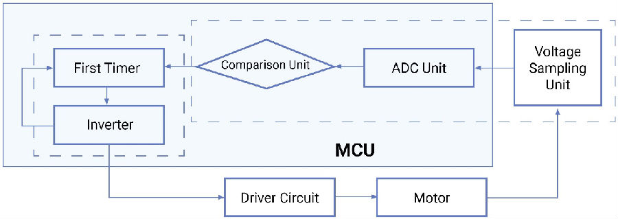
The electronic commutation of the brushless DC motor can be divided into sensored and sensor-less type. The sensorless electronic commutation has more advantages in terms of volume and cost. The sensorless brushless DC motor control method mainly detects the zero-crossing signal of the back electromotive force (EMF) of the motor through an analog-to-digital converter (ADC) or a comparator. Although the method and algorithm for the analog-to-digital converter to collect the back-EMF is more complicated, it is usually preferred since many MCUs include an ADC, saving the costs of the three components. The ADC needs to sample at a specific point in time and then compare it with the zero-crossing point through software to obtain the commutation time of the brushless DC motor to predict the next commutation time of the BLDC motor.

Figure 3: Brushless DC motor system block diagram
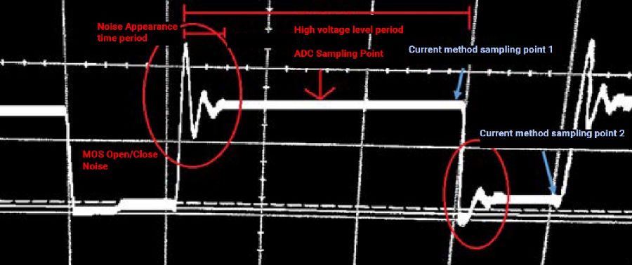
Due to the switching noise of the field effect transistor (MOSFET) when the drive signal of the brushless DC motor is switched between high level and low level, its waveform often has large fluctuations which can cause inaccurate sampling of back-EMF and the motor fails to work optimally. Therefore, it is a requirement to further improve the existing brushless DC motor system and the control method of the brushless DC motor to solve the above mentioned problems.
GD32 MCU Product Overview
Since the launch of the first Arm Cortex-M core based 32-bit general-purpose MCUs in 2013, GigaDevice GD32 MCUs has become a leader in the China’s Arm 32-bit general-purpose microcontroller market. GD32 MCU provides a variety of Arm core product combinations such as Cortex-M3/M4/M23/M33, while in August 2019 it also launched the world's first open source instruction set architecture (ISA) RISC-V core general-purpose 32-bit MCU. The GD32 MCU family provides a wide coverage with more than 370 product models in 28 product series, serving the different development and design needs of more than 20,000 customers worldwide. With annual shipments exceeding 150 million pcs and cumulative shipments exceeding 500 million, it continues to lead the Chinese MCU market with a compound annual sales growth rate of 201%.

Figure 4: GigaDevice GD32 MCU product family
The GD32E50x series of MCUs integrates an ultra-high-precision timer (SHRTimer), with 5 independent counters inside that can generate 5 groups of 2 PWM control signals supporting dead time complementary output. The signal’s frequency can reach up to 11.5GHz with highest resolution of 90ps. Due to its advance integration with other peripherals, this allows to generate various high-frequency waveforms required for motor control.
Also integrated is a 12-bit high-performance ADC with a sampling rate of 2.6MSPS which supports 16 reusable channels and 16-bit hardware oversampling with configurable resolution and filtering function. This helps to collect the Back-EMF voltage efficiently and improve the motor control accuracy.
Additionally, there is a complete DSP instruction set, support for parallel computing capabilities and single-precision floating-point unit (FPU) is included. This meets the requirements of FOC (field-oriented control) algorithms for MCU processing performance and ensuring that the motor can run efficiently. The ability to achieve precise speed control with excellent dynamic response, coupled with the low torque fluctuation of FOC allows the motor to maintain smooth operation when running, starting and braking.
In terms of on-chip peripherals, the GD32 MCUs are also equipped with a variety of analog and communication interfaces including DAC, USART, I2C, SPI, USB, high-speed operational amplifiers and comparators. At the same time, the production process is constantly evolving and the latest products have adopted the 40nm process for stable mass production, achieving industry-leading energy consumption and low cost performance ratio.
The GD32 MCU also has excellent electrostatic protection (ESD) and electromagnetic compatibility (EMC) capabilities. All products meet industrial-grade high reliability and temperature standards so that it can easily respond to various motor control application design requirements with a comprehensive configuration.
Introduction of GD32 motor control methods
In order to solve the problem of noise inserted in the system by the field effect transistor state changes, we provide a brushless DC motor system and a control method based on the GD32 MCU series. Using different duty cycles of the driving signal and selecting different sampling points to obtain an accurate back-EMF voltage, it can greatly improve the stability of motor operation.
Back-EMF sampling at a predetermined time
On the driving circuit and during the operating phase of each high-side bridge, the predetermined time is set in the high-level phase of the driving signal and is close to the falling edge of the high-level phase, or is set in the low level stage of the driving signal and is close to the rising edge of the low-level phase. This avoids the influence of switching noise of the field effect transistor on the analog-to-digital converter sampling point.
Determine the duty cycle and select the sampling point
When the duty cycle is lower than 50%, the sampling point is set at the off period of the MOS channel. When the duty cycle is higher than 50%, the sampling point is set at the on period of the MOS channel and the sampling point is changed from the middle point to before the MOS channel state changes. This happens because when the field-effect transistor in the drive circuit is turned on, the sampling voltage of the voltage sampling unit is the voltage obtained by superimposing one-half of the bus voltage (i.e. the power supply voltage of the drive circuit) on the back electromotive force. Therefore, the comparison unit compares the sampling result with one-half of the bus voltage. If the voltage of the two adjacent sampling results changes from less than one-half bus voltage to more than one-half bus voltage or from more than one-half bus voltage to less than one-half bus voltage, then that is the zero point of the back EMF.
When the field effect transistor in the driving circuit is turned off, the sampled voltage of the voltage sampling unit is the back electromotive force and the back electromotive force itself changes from negative to positive or from positive to negative according to the rotor position change. However, due to the influence of the reverse diode in the field effect transistor on the driving circuit, the negative back EMF will be pulled close to 0V, so the back EMF collected during the off period of the field effect transistor is compared with 0. If the voltage of two adjacent sampling results changes from 0V to positive or from positive to 0V, it is the zero-crossing point of the back electromotive force.

Figure 5: Schematic diagram of sampling points of the scheme
With this method, when the duty cycle is relatively low, the high level time is relatively short but the low level time is long and sampling during the low level period can have enough time to avoid the noise when the MOS is turned off. Similarly, sampling when the high duty cycle MOS channel is turned on can also avoid the noise when the MOS channel is turned on. Therefore, an accurate back-EMF voltage can be obtained regardless of the duty cycle so as to provide an accurate back-EMF signal for the MCU to calculate the commutation time of the BLDC motor.
Accurate back-EMF signals can give BLDC an excellent advantage in many areas. Increased accuracy can result in less motor power losses and higher control accuracy. This solution can be widely used in industrial automation, instrumentation, medical, consumer electronics, automobiles and other fields that require high-precision motor control.


